🔧 Building Complex Materials
Real-world surfaces are rarely simple—a concrete floor has cracks filled with dirt, a metal panel shows rust creeping from the edges, a forest floor blends grass, soil, and fallen leaves. In this lesson, you'll learn to combine textures and effects using math operations, creating materials that tell visual stories.
🎯 Learning Objectives
By the end of this lesson, you will be able to:
- Use essential math nodes (Add, Multiply, Lerp) to combine and modify textures
- Explain how Lerp (Linear Interpolation) blends between two inputs using a mask
- Create Material Functions for reusable material logic
- Implement texture blending techniques for multi-surface materials
- Set up world-aligned textures that ignore mesh UVs
- Build a terrain blend material that transitions between multiple surfaces
Estimated Time: 50-60 minutes
Prerequisites: Lesson 3.2 - Texture Basics
In This Lesson
Using Math Nodes for Effects
The Material Editor isn't just about connecting textures to outputs—it's a visual programming environment where you manipulate data using mathematical operations. Every color is a set of numbers. Every texture is a grid of numbers. By applying math to these numbers, you can create effects that go far beyond simple texture mapping.
Think of it this way: if textures are your ingredients and the material output is your finished dish, math nodes are your cooking techniques—the chopping, mixing, seasoning, and layering that transform raw ingredients into something greater than the sum of its parts.
Numbers Behind the Colors
Before diving into specific nodes, remember that everything in the Material Editor is ultimately numbers:
A color is three numbers (RGB), each ranging from 0 to 1. Black is (0, 0, 0). White is (1, 1, 1). Bright red is (1, 0, 0).
A grayscale value is a single number from 0 (black) to 1 (white).
A texture sample outputs numbers at each pixel—RGB values for color textures, a single value for grayscale masks.
When you understand that you're manipulating numbers, operations like "multiply two textures together" become intuitive: you're just multiplying the numbers at each corresponding pixel.
Figure: Every color is represented as RGB values between 0 and 1.
Essential Math Node Categories
Unreal's Material Editor provides dozens of math nodes, but you'll use a handful constantly:
Figure: These math nodes form the foundation of complex material effects. Lerp is especially important!
✅ Pro Tip: Keyboard Shortcuts
Speed up your workflow with these shortcuts—hold the key and click to create the node:
A = Add | M = Multiply | D = Divide | O = OneMinus
L = Lerp | 1/2/3/4 = Constant with 1/2/3/4 components
Lerp, Multiply, Add Operations
Of all the math nodes, three stand out as absolutely essential: Lerp, Multiply, and Add. Master these, and you can create the vast majority of material effects.
Multiply: The Workhorse
The Multiply node does exactly what it sounds like—it multiplies input A by input B. But the applications are surprisingly versatile:
Tinting colors: Multiply a texture by a color to tint it. Multiplying by (1, 0.5, 0.5) makes the image more red by reducing green and blue.
Adjusting intensity: Multiply by a single value to brighten (values > 1) or darken (values < 1) a texture.
Masking: Multiply a texture by a black-and-white mask. Where the mask is white (1), the texture shows fully. Where the mask is black (0), the result is black.
Figure: Multiply is incredibly versatile—tinting, adjusting brightness, and masking all use the same node.
Add: Layering and Brightening
The Add node sums two inputs together. Unlike Multiply, which can only make things darker or unchanged (when multiplying by values ≤ 1), Add can push values higher:
Adding light effects: Add emissive glow on top of a base color.
Combining masks: Add two masks together to create a combined effect area.
Shifting values: Add a constant to UV coordinates to offset textures.
⚠️ Watch Out
Adding values can push results above 1.0, which can cause unexpected results. For Base Color, values above 1 may not look different, but for Roughness or other clamped inputs, you might get strange behavior. Use a Saturate or Clamp node after Add if you need to ensure values stay in the 0-1 range.
Lerp: The Master Blender
If you learn only one math node, make it Lerp (Linear Interpolation). This node blends between two inputs based on a third "alpha" input, and it's the foundation of almost every texture blending technique.
📖 How Lerp Works
Inputs:
• A: The first value (shown when Alpha = 0)
• B: The second value (shown when Alpha = 1)
• Alpha: The blend factor (0 = all A, 1 = all B, 0.5 = 50/50 mix)
Formula: Result = A + (B - A) × Alpha
The magic of Lerp is that the Alpha input doesn't have to be a single value—it can be a texture! This means you can use a grayscale mask to control where each input shows through:
Figure: Lerp uses the Alpha input to blend between A and B. A mask texture creates smooth transitions.
Practical Lerp Examples
Here are common scenarios where Lerp shines:
Terrain blending: Lerp between grass and dirt textures using a painted vertex color or height map as alpha.
Weathering effects: Lerp between clean metal and rusty metal using an edge-wear mask.
Detail variation: Lerp between two color variations using a noise texture for natural-looking randomness.
Parameter-driven changes: Lerp between two states using a scalar parameter, allowing real-time control in Material Instances.
flowchart TD
    subgraph Inputs["Lerp Inputs"]
        A["Texture/Color A"]
        B["Texture/Color B"]
        Alpha["Alpha Source"]
    end

    subgraph AlphaSources["Common Alpha Sources"]
        Mask["Grayscale Mask Texture"]
        Vertex["Vertex Colors"]
        Height["Height/Slope Data"]
        Param["Scalar Parameter"]
        Noise["Noise Texture"]
    end

    subgraph Output["Lerp Output"]
        Result["Blended Result\n(A where black, B where white)"]
    end

    A --> Result
    B --> Result
    Alpha --> Result

    Mask --> Alpha
    Vertex --> Alpha
    Height --> Alpha
    Param --> Alpha
    Noise --> Alpha

    style Result fill:#667eea,color:#fff
Figure: Lerp can use many different alpha sources depending on the effect you need.
✅ Pro Tip: OneMinus for Inversion
Need to flip which texture shows where? Use the OneMinus node (shortcut: O) on your alpha input. OneMinus calculates (1 - input), turning black into white and vice versa. This inverts the blend direction without needing to re-author your mask texture.
Creating Material Functions for Reusability
As your materials grow more complex, you'll find yourself recreating the same node networks over and over. Need UV tiling controls? You build the same TexCoord → Multiply → Add setup. Want a height-based blend? Same Lerp configuration every time. This repetition wastes time and makes updates painful—if you improve the logic, you have to update every material manually.
Material Functions solve this problem elegantly. They're reusable node networks that you build once and use anywhere, like functions in programming. Change the function, and every material using it updates automatically.
📖 Definition
Material Function: A self-contained, reusable piece of material logic that can be shared across multiple materials. Functions have defined inputs and outputs, encapsulating complexity behind a simple interface.
When to Create a Material Function
Consider creating a Material Function when:
You're repeating the same node pattern in multiple materials (UV manipulation, color adjustments, blend logic)
The logic is complex and clutters your main material graph
You want consistent behavior across your project (all materials should tint the same way)
You anticipate changes—updating one function is easier than updating dozens of materials
flowchart LR
    subgraph Without["Without Material Functions"]
        M1["Material A\n(duplicate nodes)"]
        M2["Material B\n(duplicate nodes)"]
        M3["Material C\n(duplicate nodes)"]
    end

    subgraph With["With Material Functions"]
        MF["MF_TilingControls\n(single source)"]
        MA["Material A"]
        MB["Material B"]
        MC["Material C"]
        MF --> MA
        MF --> MB
        MF --> MC
    end

    style MF fill:#4CAF50,color:#fff
Figure: Material Functions eliminate duplicate node networks and centralize logic.
Creating Your First Material Function
Let's create a simple but useful function: adjustable UV tiling with offset controls.
Step 1: In the Content Browser, right-click (or click +Add) and choose Material Function from the creation menu. Name it MF_TilingControls.
Step 2: Double-click to open the Material Function Editor. It looks similar to the Material Editor but without the main material output node.
Step 3: Create the inputs your function needs. Right-click and search for FunctionInput. Create three of these:
- First input: Set Input Name to "Tiling", Input Type to "Scalar", Preview Value to 1.0
- Second input: Name it "OffsetU", type Scalar, preview 0.0
- Third input: Name it "OffsetV", type Scalar, preview 0.0
Step 4: Build the node logic:
- Add a TextureCoordinate node
- Add a Multiply node—connect TexCoord to A, Tiling input to B
- Add an Append node—connect OffsetU to A, OffsetV to B (this creates a 2D vector)
- Add an Add node—connect Multiply result to A, Append result to B
Step 5: Create the output. Right-click and add a FunctionOutput node. Name it "UVs" and connect the Add result to it.
Figure: A complete Material Function with inputs, processing nodes, and output.
Using Material Functions
Once saved, your Material Function appears in the Content Browser like any other asset. To use it in a material:
Drag and drop: Drag the function from Content Browser directly onto your material graph.
Right-click search: Right-click in the material and search for your function name.
The function appears as a single node with your defined inputs on the left and outputs on the right. Connect its output to your Texture Sample UVs, and feed parameters or constants into its inputs.
✅ Pro Tip: Built-in Material Functions
Unreal includes hundreds of pre-built Material Functions! In the material editor, right-click and browse the "Material Functions" category, or search for functions like:
BlendAngleCorrectedNormals - Properly blend two normal maps
CheapContrast - Quick contrast adjustment
FuzzyShading - Soft, fabric-like shading
HeightLerp - Blend textures based on height with adjustable contrast
Material Function Best Practices
Name clearly: Use the MF_ prefix and descriptive names (MF_TilingControls, MF_RustBlend, MF_SnowCoverage).
Document with comments: Add comment nodes inside your function explaining what it does and how to use it.
Set sensible defaults: Preview values in FunctionInput nodes should produce reasonable results when the function is first added.
Keep them focused: Each function should do one thing well. Combine multiple simple functions rather than creating one massive function.
⚠️ Watch Out
Material Functions are compiled into every material that uses them. Very complex functions can increase shader compilation time and instruction count. Check your material's Stats panel (Window → Stats in the Material Editor) to monitor instruction counts if performance becomes a concern.
Texture Blending Techniques
Now that you understand the tools—Lerp, Multiply, and Material Functions—let's explore practical techniques for blending textures. These techniques form the foundation of realistic environment materials.
Simple Two-Texture Blend
The most basic blend uses a single mask to transition between two complete texture sets (each with Base Color, Normal, Roughness):
Figure: A complete two-texture blend requires three Lerp nodes sharing the same alpha mask.
The critical point: use the same blend mask for all three Lerp nodes (Base Color, Normal, Roughness). This ensures the surface properties stay aligned—you don't want grass color appearing where dirt roughness is.
Height-Based Blending
Simple Lerp blending produces soft, gradient transitions. But real surfaces don't blend that way—dirt accumulates in cracks, snow sits on top of surfaces, moss grows in crevices. Height-based blending creates these natural transitions.
The technique uses a height map (grayscale texture where white = high, black = low) to modify the blend mask:
flowchart LR
    subgraph Inputs
        H1["Height Map A\n(e.g., grass bumps)"]
        H2["Height Map B\n(e.g., dirt cracks)"]
        Mask["Base Blend Mask"]
    end

    subgraph Process["Height Blend Logic"]
        Calc["Compare heights\nat each pixel"]
        Adj["Adjust blend based\non which surface is 'higher'"]
    end

    subgraph Result
        Out["Sharp, natural\ntransitions"]
    end

    H1 --> Calc
    H2 --> Calc
    Mask --> Adj
    Calc --> Adj
    Adj --> Out

    style Out fill:#4CAF50,color:#fff
Figure: Height-based blending considers surface elevation to create natural transitions.
Unreal provides a built-in Material Function called HeightLerp that handles this calculation. It takes two height values, a blend factor, and a contrast parameter to control transition sharpness.
✅ Pro Tip: Contrast Control
The HeightLerp function's contrast parameter is powerful:
Low contrast (0.1-0.3): Softer transitions, useful for subtle blends
Medium contrast (0.5-0.7): Natural-looking transitions for most cases
High contrast (0.8-1.0): Sharp, almost binary transitions where height difference is extreme
Vertex Color Blending
So far, our blend masks have been textures. But what if you want to paint blend zones directly on your mesh? That's where vertex colors come in.
Vertex colors are RGBA values stored at each vertex of a mesh. Artists can paint these values in Unreal's Mesh Paint mode or in 3D modeling software. The colors interpolate smoothly between vertices, creating gradients across faces.
To use vertex colors as a blend mask:
1. Add a VertexColor node to your material (right-click → search "VertexColor")
2. Connect one of its channels (R, G, B, or A) to your Lerp's Alpha input
3. In the editor, switch to Mesh Paint mode (Shift+4) and paint on your mesh
Figure: Vertex colors let artists hand-paint blend zones directly on meshes.
Vertex color blending is incredibly powerful for environmental art because it gives artists direct control over exactly where materials transition, without needing to create unique mask textures for every mesh.
💡 Multi-Material Blending
Since vertex colors have four channels (R, G, B, A), you can blend up to five different materials on a single mesh:
• Base material (where all channels are 0)
• Red channel material
• Green channel material
• Blue channel material
• Alpha channel material
This technique is commonly used for terrain and large environmental pieces.
⚠️ Watch Out
Vertex colors are stored per-vertex, not per-pixel. On low-poly meshes, blends will appear blocky because there aren't enough vertices for smooth gradients. Either increase mesh density in blend areas or use a combination of vertex colors and texture masks for finer detail.
World-Aligned Textures
Sometimes mesh UVs are the enemy. Imagine texturing a rocky cliff made of dozens of separate mesh pieces. Even with perfect UV unwrapping, seams appear where meshes meet because each piece's UVs are independent. Or consider a modular building system—every wall section needs identical texturing at joints, but slight UV differences create visible mismatches.
World-aligned textures solve this by ignoring mesh UVs entirely. Instead, they project textures based on the object's position in world space. Adjacent surfaces sample the same texture coordinates at their shared edges, creating seamless transitions regardless of how the meshes are constructed.
📖 Definition
World-Aligned Texturing: A technique where texture coordinates are derived from an object's world position rather than its UV map. The texture effectively "floats" in 3D space, and surfaces sample from wherever they intersect that space.
How World Alignment Works
Instead of using the TexCoord node (which reads mesh UVs), world-aligned textures use the WorldPosition node. This node outputs the XYZ coordinates of each pixel in world space.
By dividing the world position by a tiling value, you control how frequently the texture repeats. A larger divisor means larger texture tiles.
Figure: World-aligned textures eliminate seams between adjacent mesh pieces.
Basic World-Aligned Setup
Here's the node setup for basic world-aligned texturing:
1. Add a WorldPosition node (search "Absolute World Position")
2. Add a Divide node. Connect WorldPosition to A, and a constant (your tile size in Unreal units) to B. A value of 100 means the texture repeats every 100 units (1 meter by default).
3. Use a ComponentMask node to extract two channels (e.g., X and Y for horizontal surfaces, or X and Z for vertical walls)
4. Connect the result to your Texture Sample's UVs input
flowchart LR
    WP["WorldPosition\n(Absolute)"] --> DIV["Divide"]
    SIZE["Scalar: 512\n(tile size)"] --> DIV
    DIV --> MASK["ComponentMask\n(select 2 channels)"]
    MASK --> TS["Texture Sample\nUVs"]

    style WP fill:#9C27B0,color:#fff
    style SIZE fill:#4CAF50,color:#fff
    style TS fill:#667eea,color:#fff
Figure: Basic world-aligned texture coordinate setup.
Tri-Planar Projection
Basic world alignment has a flaw: it only works well for surfaces facing one direction. A floor uses XY coordinates, but what about walls facing different directions? The texture stretches horribly on surfaces perpendicular to your chosen plane.
Tri-planar projection solves this by sampling the texture three times—once for each axis plane (XY, XZ, YZ)—then blending between them based on the surface normal. Surfaces facing up/down use XY, forward/back use XZ, and left/right use YZ.
Figure: Tri-planar projection samples three orientations and blends based on surface normal.
Unreal includes a built-in WorldAlignedTexture Material Function that handles tri-planar projection automatically. Simply search for it in the material editor and connect your texture and tiling values.
✅ Pro Tip: When to Use World-Aligned Textures
Great for: Terrain, large rock formations, modular architecture, cliff faces, anything made of many mesh pieces that should look continuous
Avoid for: Unique props with specific UV layouts, characters, anything with intentional texture placement (logos, decals, control panels)
Performance Considerations
World-aligned and tri-planar textures have tradeoffs:
Tri-planar costs 3× the texture samples compared to standard UV mapping. Each pixel samples three times, which can impact performance on complex scenes.
Blending seams between planes can be visible on surfaces at 45-degree angles if the blend falloff isn't tuned properly.
For large environments, consider using world-aligned textures only where needed (terrain, distant rocks) and standard UVs for hero assets that players see up close.
⚠️ Watch Out
World-aligned textures don't move with objects! If you move a mesh, its texture coordinates change because they're based on world position. This is usually fine for static environment pieces but problematic for moving or animated objects. For those, stick with standard UV mapping.
🏋️ Hands-On: Create a Terrain Blend Material
Let's apply everything from this lesson to create a practical material: a terrain surface that blends between grass and dirt using a mask texture. This technique is used in virtually every game with outdoor environments.
What You'll Create
A two-layer terrain material with adjustable blend mask, tiling controls for each layer, and proper PBR channel blending.
Estimated Time: 25-35 minutes
Step 1: Gather Your Textures
You'll need two texture sets. From Starter Content or downloaded PBR textures, gather:
Grass set: Base Color, Normal, Roughness (or a combined ORM texture)
Dirt/Ground set: Base Color, Normal, Roughness
Blend mask: Any grayscale texture can work—noise, grunge, or a painted mask
🔍 Hint: Don't have textures?
Starter Content includes grassy and rocky textures. You can also use solid colors instead of textures for testing—the blend logic works the same way. Just use Constant3Vector nodes for colors and Constant nodes for roughness values.
Step 2: Create the Material
Create a new material called M_TerrainBlend. Open it in the Material Editor.
First, set up your texture samples. Create six Texture Sample nodes (or four if using color-only for testing):
- Grass Base Color
- Grass Normal
- Grass Roughness (or extract from ORM)
- Dirt Base Color
- Dirt Normal
- Dirt Roughness
Create one more Texture Sample for your blend mask texture.
Step 3: Add Tiling Parameters
We want independent tiling control for each texture layer.
Create two Scalar Parameters:
Grass_Tiling(default: 4.0)Dirt_Tiling(default: 4.0)
Create two TextureCoordinate nodes and two Multiply nodes to scale UVs separately for each texture set.
Connect the appropriate tiled UVs to each texture's UV input—all grass textures share one UV setup, all dirt textures share another.
🔍 Hint: Organizing your graph
Material graphs get messy fast! Use Comment boxes (select nodes, press C) to group related nodes. Create sections for "Grass Layer," "Dirt Layer," "Blend Logic," and "Output." This makes the graph much easier to read and maintain.
Step 4: Create the Blend Logic
Now for the core of the material—blending with Lerp nodes.
Create three Lerp nodes for Base Color, Normal, and Roughness:
Base Color Lerp:
- A input: Grass Base Color RGB
- B input: Dirt Base Color RGB
- Alpha input: Blend mask (Red channel or RGB if grayscale)
Normal Lerp:
- A input: Grass Normal RGB
- B input: Dirt Normal RGB
- Alpha input: Same blend mask as above
Roughness Lerp:
- A input: Grass Roughness (R channel)
- B input: Dirt Roughness (R channel)
- Alpha input: Same blend mask
⚠️ Critical: Share the Same Alpha!
All three Lerp nodes must use the exact same blend mask input. Don't create separate mask samples—route one mask texture to all three Alpha pins. This ensures your Base Color, Normal, and Roughness stay perfectly aligned.
Step 5: Add Blend Control Parameter
Let's make the blend adjustable without changing the mask texture.
Create a Scalar Parameter called Blend_Contrast (default: 0.5, range 0-1).
Before the mask goes into the Lerp nodes, add processing:
- Create a Subtract node: Mask - 0.5 (centers the mask around zero)
- Create a Multiply node: Result × Blend_Contrast × 2 (adjusts contrast)
- Create an Add node: Result + 0.5 (re-centers)
- Create a Saturate node: Clamps result to 0-1
Use this processed mask for all three Lerp Alpha inputs. Now the Blend_Contrast parameter lets you sharpen or soften the transition in Material Instances!
Step 6: Connect Outputs
Wire your Lerp outputs to the main material node:
- Base Color Lerp → Base Color
- Normal Lerp → Normal
- Roughness Lerp → Roughness
Click Apply and Save.
Figure: Logical overview of the terrain blend material structure.
Step 7: Test and Create Instances
Apply your material to a large plane or landscape in your level. Create a Material Instance and experiment with the parameters:
- Adjust Grass_Tiling and Dirt_Tiling to control texture repetition
- Adjust Blend_Contrast to sharpen or soften transitions
- Try different blend mask textures in the instance
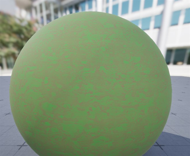
Figure: The terrain blend rendered on the Material Editor preview sphere · grass green and dirt brown are combined with a Lerp driven by a noise mask, giving natural, patchy transitions.
✅ Success Check: How do you know it worked?
Your terrain blend material is working correctly if:
- You see both grass and dirt textures on the surface
- The blend follows the mask pattern (where mask is dark = grass, white = dirt, or vice versa)
- Lighting responds correctly to both areas (normal maps working)
- Each area has correct roughness (grass might be slightly shinier, dirt more matte)
- Changing tiling parameters affects each layer independently
- Blend Contrast parameter sharpens/softens the transition
🎉 Excellent Work!
You've built a production-quality terrain blend material! This same architecture scales to more complex setups—add more layers, use vertex colors instead of mask textures, incorporate height blending, or add detail textures. The fundamentals you've learned here apply to all of them.
Summary
This lesson equipped you with the tools to build sophisticated, multi-layered materials. Let's review the key concepts:
Math nodes are your creative toolkit. Add, Multiply, Divide, and especially Lerp transform simple textures into complex, controllable effects. Understanding that colors are just numbers opens up endless possibilities.
Lerp is the master blender. With two inputs and an alpha mask, Lerp creates smooth transitions between any values—colors, roughness, entire texture sets. The alpha can be a constant, parameter, texture, vertex color, or calculated value.
Material Functions promote reusability. Encapsulate common node patterns into functions to eliminate duplication, centralize updates, and keep your material graphs clean and maintainable.
Texture blending follows patterns. Whether using simple Lerp, height-based blending, or vertex colors, the same architecture applies: blend each PBR channel with the same alpha mask to keep properties aligned.
World-aligned textures solve seaming problems. By deriving UV coordinates from world position, adjacent mesh pieces texture seamlessly—essential for terrain, modular architecture, and large environmental pieces.
🔑 Key Takeaways
- Multiply: tinting, masking, intensity adjustment
- Add: combining effects, offsetting values
- Lerp: blending A→B controlled by Alpha (0-1)
- Same alpha mask must drive ALL blended channels
- Material Functions: create once, use everywhere
- HeightLerp: natural transitions using height data
- Vertex colors: paint blend zones directly on meshes
- World-aligned: seamless texturing across mesh boundaries
- Tri-planar: world-aligned on any surface orientation
What's Next?
In the next lesson, Material Instances and Parameters, you'll dive deeper into the parameter system—creating well-organized parameter groups, using Static Switch parameters for material variants, and building efficient material libraries that artists can customize without touching the parent material.