🖼️ Texture Basics
Textures are the images that bring your materials to life—the wood grain on a table, the rust on a metal pipe, the fabric weave on a character's clothing. In this lesson, you'll learn how to import, configure, and use textures effectively in Unreal Engine.
🎯 Learning Objectives
By the end of this lesson, you will be able to:
- Identify which texture formats work best for different use cases in Unreal Engine
- Import textures correctly using the Content Browser
- Configure texture settings including compression, mipmaps, and sRGB
- Explain UV mapping fundamentals and how textures wrap onto 3D surfaces
- Use Texture Coordinate nodes to control tiling and offset
- Apply textures to a material using the Texture Sample node
Estimated Time: 40-50 minutes
Prerequisites: Lesson 3.1 - Material Fundamentals
In This Lesson
Supported Texture Formats
Before you can use a texture in Unreal Engine, you need to have it in a compatible format. Think of texture formats like different languages—Unreal speaks some fluently, understands others with effort, and can't read a few at all.
Unreal Engine supports a variety of image formats, but not all are created equal. Your choice of format affects import speed, quality preservation, and how much control you have over the final result.
Recommended Formats
These formats work excellently with Unreal Engine and should be your go-to choices:
Figure: PNG and TGA are the best general-purpose formats. Use EXR/HDR for high dynamic range needs.
✅ Pro Tip
When in doubt, use PNG. It's lossless (no quality degradation), supports transparency, and every image editing program can create it. For production pipelines, TGA is equally excellent and is the traditional game industry standard.
Why Format Matters
You might wonder: "Unreal compresses textures anyway, so why does the source format matter?" Great question!
When you import a texture, Unreal converts it to an internal format optimized for your target platform. But the quality of that conversion depends entirely on what you start with. If you import a heavily-compressed JPEG, Unreal is working with already-degraded data. Artifacts from JPEG compression get baked into the final texture permanently.
Think of it like photocopying a photocopy—each generation loses quality. Start with the best source possible, and Unreal's compression will preserve maximum detail.
flowchart LR
    subgraph Source["Source Image"]
        PNG["PNG/TGA\n(Lossless)"]
        JPG["JPEG\n(Already Lossy)"]
    end

    subgraph Import["Unreal Import"]
        I["Compression\n& Processing"]
    end

    subgraph Result["In-Engine Quality"]
        Good["✓ Maximum Detail\nClean edges\nNo artifacts"]
        Bad["✗ Degraded Quality\nBlurry details\nCompression artifacts"]
    end

    PNG --> I
    JPG --> I
    I --> Good
    I --> Bad

    PNG -.->|"produces"| Good
    JPG -.->|"produces"| Bad

    style Good fill:#4CAF50,color:#fff
    style Bad fill:#e74c3c,color:#fff
Figure: Your source format determines the ceiling for final in-engine quality.
Texture Resolution Guidelines
Unreal Engine works best with textures that have power-of-two dimensions: 256×256, 512×512, 1024×1024, 2048×2048, 4096×4096, and so on. While Unreal can handle non-power-of-two textures, they won't generate mipmaps correctly and may have performance implications.
Textures don't need to be square. A 2048×1024 texture is perfectly valid—just keep both dimensions as powers of two.
💡 Common Texture Sizes
Here's when to use different resolutions:
512×512: Small props, distant objects, UI elements
1024×1024 (1K): Standard props, secondary characters
2048×2048 (2K): Main characters, hero props, close-up surfaces
4096×4096 (4K): Large surfaces (walls, terrain), cinematics, photogrammetry
⚠️ Watch Out
Bigger isn't always better! A 4K texture uses 4× the memory of a 2K texture. If a texture is only seen from far away, that extra detail is wasted. Choose resolution based on how closely players will see the surface—not just "the highest I have."
Importing Textures Properly
Getting textures into Unreal Engine is straightforward, but doing it properly requires understanding a few key steps. Let's walk through the import process and the decisions you'll make along the way.
Basic Import Methods
Unreal offers several ways to import textures:
Drag and Drop: The simplest method. Drag image files directly from your file explorer into the Content Browser. Unreal creates texture assets automatically.
Import Button: Click the Import button in the Content Browser toolbar, then browse to select your files. This gives you more control over import settings before the files are added.
Right-Click Menu: Right-click in the Content Browser, select Import to..., and choose your files.
Figure: All three methods achieve the same result. Drag and drop is fastest for quick imports.
The Import Dialog
When you import multiple textures at once (especially using the Import button), Unreal shows an import dialog with options. For textures, you'll typically see options like:
Import All: Accepts default settings for all selected files.
Import: Imports individual files, letting you review each one.
For most texture imports, the defaults work fine. However, Unreal makes assumptions about your textures based on their names—and sometimes those assumptions are wrong.
Automatic Detection (and When It Fails)
Unreal tries to be smart about detecting texture types. If your file is named brick_normal.png, Unreal assumes it's a normal map and configures settings accordingly. Similarly, wood_basecolor.tga gets treated as a color texture.
This auto-detection works great when you follow standard naming conventions. But if your texture is named something generic like texture_01.png, Unreal guesses—and may guess wrong.
💡 Naming Conventions That Trigger Auto-Detection
Include these suffixes in your filenames for automatic configuration:
_BaseColor, _Diffuse, _Albedo, _D: Color texture (sRGB enabled)
_Normal, _N: Normal map (linear, specific compression)
_Roughness, _R: Roughness map (linear, grayscale)
_Metallic, _M: Metallic map (linear, grayscale)
_AO, _AmbientOcclusion: Ambient occlusion (linear)
_Emissive, _E: Emissive texture (sRGB enabled)
Organizing Imported Textures
Before importing, create a logical folder structure. A common approach:
flowchart TD
    Content["📁 Content"]
    Content --> Textures["📁 Textures"]
    Textures --> Env["📁 Environment"]
    Textures --> Char["📁 Characters"]
    Textures --> Props["📁 Props"]
    Textures --> UI["📁 UI"]

    Env --> Brick["📁 Brick"]
    Brick --> T1["🖼️ T_Brick_BaseColor"]
    Brick --> T2["🖼️ T_Brick_Normal"]
    Brick --> T3["🖼️ T_Brick_Roughness"]

    style Content fill:#667eea,color:#fff
    style Textures fill:#4CAF50,color:#fff
Figure: Organize textures by category and material type for easy management.
Use a consistent prefix for texture assets. The convention T_ (for Texture) makes textures easy to find when searching. For example: T_Brick_BaseColor, T_Brick_Normal, T_Metal_Roughness.
✅ Pro Tip
Keep texture sets together! When you have T_Brick_BaseColor, T_Brick_Normal, and T_Brick_Roughness, they should all be in the same folder. This makes it easy to find all textures for a single material and helps with asset management in larger projects.
Texture Settings: Compression, Mipmaps, sRGB
Once a texture is imported, you can fine-tune how Unreal handles it. Double-click any texture in the Content Browser to open the Texture Editor, where you'll find a wealth of settings. Let's focus on the three most important ones that affect quality and performance.
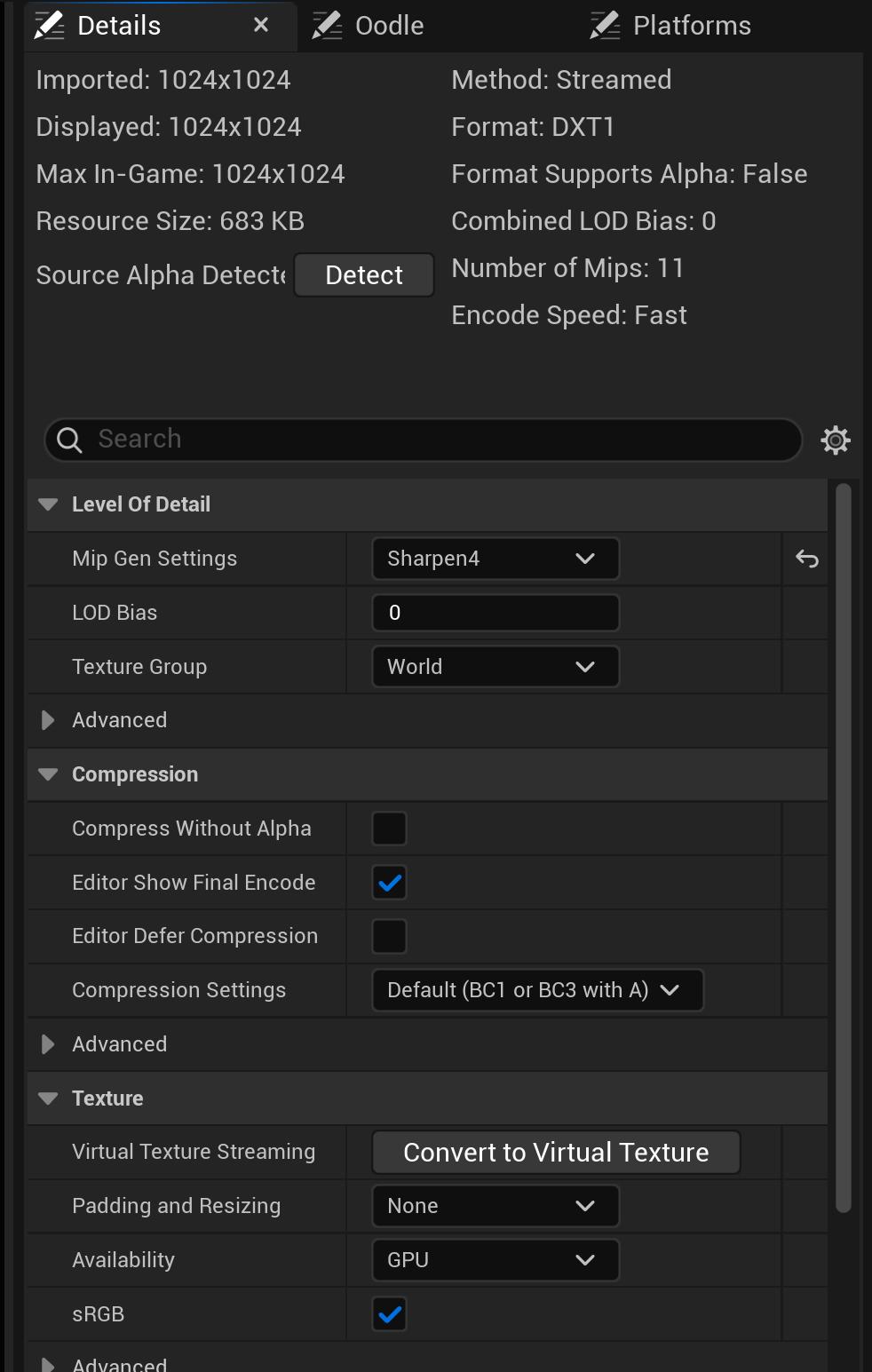
Figure: The Texture Editor Details panel in UE 5.8. Compression Settings, sRGB, and Mip Gen Settings · the three settings covered below · all live in this panel. sRGB is enabled here because this is a color (albedo) texture; the info header also reports Number of Mips 11, the full mip chain.
Compression Settings
Unreal doesn't store textures in their original format—that would consume enormous amounts of memory. Instead, textures are compressed using GPU-friendly formats that can be decoded quickly during rendering.
The Compression Settings dropdown determines which compression algorithm Unreal uses. Different texture types need different compression:
Figure: Choose compression based on texture type, not file size concerns.
✅ Pro Tip: Channel Packing
Advanced workflows often "pack" multiple grayscale maps into a single RGB texture—for example, putting Roughness in the Red channel, Metallic in Green, and Ambient Occlusion in Blue. This reduces the number of texture samples and saves memory. When using packed textures, use "Masks" compression and disable sRGB.
Mipmaps Explained
Imagine looking at a brick wall. Up close, you can see every detail in the texture—individual scratches, mortar lines, color variations. But when that same wall is far away, it's just a tiny cluster of pixels on screen. Does it make sense to sample a 2048×2048 texture for something that's only 20 pixels tall?
Mipmaps solve this problem. A mipmap is a pre-calculated, smaller version of the texture. Unreal generates a chain of progressively smaller images: the full resolution, then half size, then quarter size, and so on, down to 1×1 pixel.
Figure: Each mip level is half the resolution of the previous one, forming a complete chain.
When rendering, the GPU automatically selects the appropriate mip level based on how large the texture appears on screen. This provides two major benefits:
Performance: Sampling a 64×64 mip is much faster than sampling a 2048×2048 texture when only a few pixels are needed.
Quality: Without mipmaps, distant textures exhibit "shimmer" or "crawling" artifacts as the camera moves. Mipmaps eliminate this by pre-filtering the texture data.
⚠️ Watch Out
Mipmaps only generate correctly for power-of-two textures (256, 512, 1024, etc.). A 1000×1000 texture can't create a proper mip chain because you can't halve odd numbers evenly. Unreal will warn you about this and may disable mipmaps for non-power-of-two textures.
You can control mipmap behavior in the texture settings:
Mip Gen Settings: Choose how mips are generated (Sharpen, Blur, etc.)
LOD Bias: Offset which mip level is selected (negative = sharper, positive = blurrier)
Never Stream: Keep all mip levels in memory (for critical textures)
sRGB: The Color Space Setting
This single checkbox causes more confusion than almost any other texture setting. Understanding sRGB requires knowing a bit about how computers store and display color.
Human eyes don't perceive brightness linearly—we're more sensitive to differences in dark tones than bright tones. The sRGB color space accounts for this by encoding images with a "gamma curve" that dedicates more precision to shadows.
The key question is: Does your texture represent colors that will be displayed, or data that will be calculated?
Figure: Enable sRGB for color textures; disable it for data textures like normal and roughness maps.
sRGB ON: The texture contains color information meant to be seen by humans. Unreal applies gamma correction during rendering so colors appear correct on your monitor.
sRGB OFF (Linear): The texture contains raw data that will be used in mathematical calculations. A roughness value of 0.5 should mean exactly 50%, not a gamma-adjusted value. Leaving sRGB on for data textures causes incorrect shading.
📖 Simple Rule
If the texture's purpose is to look like something (colors, images, emissive glow), enable sRGB.
If the texture's purpose is to store numbers (roughness values, normal directions, height data), disable sRGB.
UV Mapping Fundamentals
You have a 3D cube. You have a 2D texture. How does the engine know which part of the texture goes on which face of the cube? The answer is UV mapping—a system of coordinates that tells each point on a 3D surface where to sample from a 2D texture.
What Are UVs?
UV coordinates are like a treasure map. Every vertex on a 3D mesh has a corresponding location on a 2D grid. The letters "U" and "V" represent the horizontal and vertical axes of this 2D space (we use U and V instead of X and Y to avoid confusion with the 3D world coordinates).
Figure: UV coordinates map 2D texture pixels to 3D surface points.
UV coordinates typically range from 0 to 1, where (0,0) is one corner of the texture and (1,1) is the opposite corner. When a mesh is textured, each vertex stores its UV position, and the engine interpolates between vertices to determine the color at every pixel.
UV Unwrapping: The Art of Flattening
Creating good UVs is called "unwrapping"—you're essentially flattening a 3D shape into 2D, like peeling an orange and laying the peel flat. This is typically done in 3D modeling software (Blender, Maya, 3ds Max) before importing the mesh into Unreal.
A well-unwrapped mesh has:
Minimal stretching: UV islands maintain proportional sizes relative to the 3D surface
Efficient use of space: UV islands are packed tightly to maximize texture resolution
Logical seams: UV cuts are hidden in natural edges or less-visible areas
flowchart LR
    subgraph Modeling["3D Software"]
        A["Create Mesh"] --> B["UV Unwrap"]
        B --> C["Export FBX"]
    end

    subgraph Unreal["Unreal Engine"]
        D["Import Mesh\n(with UVs)"] --> E["Apply Material\n(with Textures)"]
        E --> F["Texture appears\ncorrectly on surface"]
    end

    C --> D

    style B fill:#667eea,color:#fff
    style E fill:#4CAF50,color:#fff
Figure: UV unwrapping happens in your modeling software before import.
Multiple UV Channels
A mesh can have multiple sets of UV coordinates, stored in different "channels." This is useful because different purposes have different requirements:
UV Channel 0: Typically used for material textures (base color, normal, roughness). Often has overlapping islands—multiple faces can share the same texture area if they should look identical.
UV Channel 1: Often used for lightmaps. Lightmap UVs must be non-overlapping because each surface point needs unique lighting data.
Unreal automatically generates lightmap UVs on import if needed, but the results aren't always optimal. For best quality, create dedicated lightmap UVs in your modeling software.
💡 For This Course
You won't need to create UVs yourself—Unreal's primitive shapes and Starter Content meshes come with proper UVs already. But understanding how UVs work helps you troubleshoot issues like stretched textures or incorrect tiling. If a texture looks distorted, the mesh's UVs are usually the cause.
⚠️ Watch Out
If you see textures appearing "stretched," "squished," or mapped incorrectly, check these common causes:
• The mesh has bad or missing UV coordinates
• The material is using the wrong UV channel
• The texture's tiling values are incorrect
• Scale was applied incorrectly during modeling
Texture Coordinates and Tiling
Now that you understand UV mapping conceptually, let's see how to control it in the Material Editor. The Texture Coordinate node (often called "TexCoord") is your primary tool for manipulating how textures are applied to surfaces.
The Texture Coordinate Node
By default, when you create a Texture Sample node, it automatically uses the mesh's UV coordinates from channel 0. But what if you want to tile the texture, offset it, or use a different UV channel? That's where the Texture Coordinate node comes in.
To add one, right-click in the Material Editor and search for "TextureCoordinate" (or press U and click). Connect its output to the UVs input of a Texture Sample node.
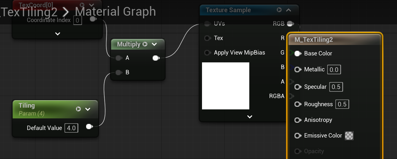
Figure: The Texture Coordinate node in a real UE 5.8 material graph. Its output feeds the Texture Sample UVs input · here through a Multiply node that scales the coordinates by a Tiling parameter (4.0) · so the texture repeats across the surface.
Tiling: Repeating Textures
The most common use for Texture Coordinates is tiling—repeating a texture across a surface. Imagine you have a 1-meter brick texture, but your wall is 10 meters wide. Without tiling, that brick texture would be stretched to 10× its intended size, making each brick look enormous.
By setting the UTiling and VTiling values in the Texture Coordinate node, you control how many times the texture repeats:
UTiling = 1, VTiling = 1: No tiling (default). The texture maps once across the UV space.
UTiling = 4, VTiling = 4: The texture repeats 4 times horizontally and 4 times vertically (16 total tiles).
UTiling = 2, VTiling = 1: The texture repeats twice horizontally but only once vertically.
Figure: Increasing tiling values makes textures repeat more times across the surface.
Dynamic Tiling with Math
Sometimes you need tiling that adjusts based on object size or other factors. Instead of hardcoding values in the Texture Coordinate node, you can multiply the UV output by a parameter.
flowchart LR
    TC["TexCoord\n(1,1)"] --> MUL["Multiply"]
    PARAM["Scalar Parameter\n'Tiling_Amount'\nDefault: 2.0"] --> MUL
    MUL --> TS["Texture Sample\nUVs input"]
    TS --> OUT["To Base Color"]

    style PARAM fill:#4CAF50,color:#fff
    style MUL fill:#FF9800,color:#fff
Figure: Multiply TexCoord by a parameter for adjustable tiling in Material Instances.
This setup lets you expose a "Tiling_Amount" parameter that can be adjusted per Material Instance—perfect for reusing the same material on different-sized surfaces.
✅ Pro Tip
For world-aligned textures (textures that should tile based on world position rather than UV coordinates), use the WorldPosition node divided by your desired tile size. This makes textures tile consistently regardless of the mesh's UVs—useful for terrain or large architectural surfaces.
Texture Offset
Besides tiling, you might want to offset (shift) a texture. This is done by adding a value to the UV coordinates before sampling:
Adding to U: Shifts the texture horizontally
Adding to V: Shifts the texture vertically
Create an Add node, connect the Texture Coordinate output to one input, and a Constant2Vector (or Vector Parameter for adjustability) to the other. The result goes to the Texture Sample's UVs.
💡 Common Use Cases for UV Manipulation
Tiling: Repeating floor tiles, brick walls, fabric patterns
Offset: Animating textures (scrolling water, conveyor belts), aligning patterns
Rotation: Matching texture direction to surface features (use a Custom Rotator node)
Channel switching: Using lightmap UVs (Channel 1) for certain effects
Selecting UV Channels
If your mesh has multiple UV sets, you can choose which one to use. In the Texture Coordinate node's Details panel, find the Coordinate Index property:
0: Primary UVs (default, used for material textures)
1: Secondary UVs (often lightmap UVs)
2, 3, etc.: Additional UV channels if the mesh has them
⚠️ Watch Out
If you select a UV channel that doesn't exist on the mesh, the texture will appear black or behave unexpectedly. Most simple meshes only have channels 0 and 1. Check your mesh's UV channels in the Static Mesh Editor if you're unsure.
🏋️ Hands-On: Apply Textures to a Material
Let's create a textured material using Unreal's Starter Content. You'll import texture files (or use existing ones), connect them properly in the Material Editor, and control tiling with a parameter.
What You'll Create
A complete PBR material with Base Color, Normal, and Roughness textures, plus adjustable tiling.
Estimated Time: 20-25 minutes
Step 1: Enable Starter Content (if needed)
If you created your project without Starter Content, you can add it now. Go to Edit → Plugins, search for "Starter Content," and enable it. Alternatively, create a new project with Starter Content included.
The Starter Content includes several texture sets we can use. Navigate to Content/StarterContent/Textures in the Content Browser.
🔍 Hint: Don't have Starter Content?
You can also download free textures from sites like ambientCG, Poly Haven, or Quixel Megascans (free with Unreal Engine). Import the textures to your project and use them instead.
Step 2: Create a New Material
In your Materials folder (or create one), right-click and select Material. Name it M_TexturedSurface. Double-click to open the Material Editor.
Step 3: Add Texture Sample Nodes
We need three Texture Sample nodes—one each for Base Color, Normal, and Roughness.
Right-click on the canvas and search for "TextureSample" (or hold T and click). Create three of these nodes and arrange them vertically on the left side of your canvas.
For each Texture Sample node, click on it and look at the Details panel. Click the dropdown next to Texture and select:
- Top node: A base color texture (e.g.,
T_Brick_Clay_New_Dor any "_D" or "_BaseColor" texture) - Middle node: A normal map (e.g.,
T_Brick_Clay_New_Nor any "_N" or "_Normal" texture) - Bottom node: A roughness texture (e.g.,
T_Brick_Clay_New_Ror any "_R" texture)
🔍 Hint: Finding matching textures
Texture sets usually share a common base name with different suffixes. For example: T_Brick_Clay_New_D (Diffuse/Color), T_Brick_Clay_New_N (Normal), T_Brick_Clay_New_R (Roughness). Look for textures with matching prefixes.
Step 4: Connect to Material Outputs
Now wire up your textures to the correct material inputs:
- Base Color texture: Connect its RGB output to the Base Color input on the Main Material Node
- Normal texture: Connect its RGB output to the Normal input
- Roughness texture: Connect its R (red channel) output to the Roughness input
⚠️ Important: Normal Map Sampler Type
When you assign a normal map texture to a Texture Sample node, Unreal should automatically detect it and set the correct Sampler Type. If the preview looks wrong (flat or has strange colors), select the normal map's Texture Sample node and in the Details panel, change Sampler Type to Normal.
Step 5: Add Tiling Control
Let's make the tiling adjustable. Create a Texture Coordinate node (press U and click).
Create a Scalar Parameter node (press S and click). Name it Tiling and set the default value to 2.0.
Create a Multiply node (press M and click). Connect:
- Texture Coordinate output → Multiply input A
- Tiling parameter output → Multiply input B
Now connect the Multiply output to the UVs input of ALL THREE Texture Sample nodes. You can drag a wire from Multiply, then hold Ctrl and click on each Texture Sample's UVs pin to connect multiple wires from one output.
Figure: The complete textured material with tiling control. All three textures share the same UV manipulation.
Step 6: Apply and Test
Click Apply, then Save. Close the Material Editor.
In your level, add a primitive shape (cube or plane works well). Drag your M_TexturedSurface material onto it.
Now create a Material Instance: right-click the material → Create Material Instance → name it MI_TexturedSurface_Tiled. Open the instance and adjust the Tiling parameter. Watch how the texture repetition changes in real-time!
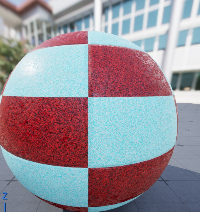
Figure: The finished material on the preview sphere in UE 5.8. The texture tiles across the surface (Tiling 4), the roughness map breaks up the specular highlights, and the normal map adds surface relief · Base Color, Normal, and Roughness all driven by one shared, tiled set of UVs.
✅ Success Check: How do you know it worked?
Your material is working correctly if:
- The surface shows the color texture (not just gray)
- Light interacts with the surface detail (you can see bumps from the normal map)
- The roughness varies across the surface (some areas shinier than others)
- Changing the Tiling parameter in the instance makes the texture repeat more or fewer times
🎉 Excellent Work!
You've created a fully-textured PBR material with adjustable tiling! This workflow—Base Color + Normal + Roughness with shared UV controls—is the foundation for virtually every surface material in professional games.
Summary
In this lesson, you've learned how to work with textures in Unreal Engine—from choosing the right file format to configuring import settings to applying textures in materials. Here's what we covered:
Texture formats matter. PNG and TGA are your best choices for source files because they're lossless. Start with the highest quality source, and let Unreal handle the compression for runtime.
Compression settings depend on texture type. Use "Default" for color textures, "Normalmap" for normal maps, and "Masks" for grayscale data like roughness. Getting this wrong causes visible artifacts.
Mipmaps improve both performance and quality by providing pre-calculated smaller versions of textures for distant surfaces. They require power-of-two dimensions to generate correctly.
sRGB is for color, Linear is for data. Enable sRGB for textures humans will see (base color, emissive). Disable it for textures that store numerical data (normal, roughness, metallic).
UV coordinates map 2D textures to 3D surfaces. Understanding UVs helps you troubleshoot stretched or incorrectly mapped textures.
Texture Coordinates control tiling and offset. Use the TexCoord node with Multiply to create adjustable tiling parameters in your materials.
🔑 Key Takeaways
- Use PNG or TGA for source textures (lossless quality)
- Power-of-two dimensions (512, 1024, 2048) for proper mipmaps
- Match compression settings to texture type
- sRGB ON for colors, OFF for data (normal, roughness, etc.)
- UV coordinates range 0-1, defined in modeling software
- Texture Coordinate × Scalar Parameter = adjustable tiling
- All PBR textures in a material should share the same UV setup
What's Next?
In the next lesson, Building Complex Materials, you'll learn to combine multiple textures and effects using math nodes. We'll explore Lerp (blend) operations, texture masking, and creating reusable Material Functions—techniques that let you build sophisticated materials like weathered surfaces, terrain blends, and dynamic effects.